An adder is a digital logic circuit in electronics that implements addition of numbers. In many computers and other types of processors, adders are used to calculate addresses, similar operations and table indices in the ALU and also in other parts of the processors. These can be built for many numerical representations like excess-3 or binary coded decimal. Adders are classified into two types: half adder and full adder. The half adder circuit has two inputs: A and B, which add two input digits and generate a carry and sum. The full adder circuit has three inputs: A and C, which add the three input numbers and generate a carry and sum. This article gives brief information about half adder and full adder in tabular forms and circuit diagrams.

Half Adder and Full Adder Circuit
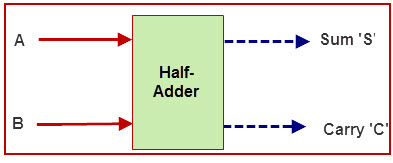
An adder is a digital circuit that performs addition of numbers. The half adder adds two binary digits called as augend and addend and produces two outputs as sum and carry; XOR is applied to both inputs to produce sum and AND gate is applied to both inputs to produce carry. The full adder adds 3 one bit numbers, where two can be referred to as operands and one can be referred to as bit carried in. And produces 2-bit output, and these can be referred to as output carry and sum.
Half Adder
By using half adder, you can design simple addition with the help of logic gates.
Let’s see an addition of single bits.
0+0 = 0
0+1 = 1
1+0 = 1
1+1 = 10
These are the least possible single-bit combinations. But the result for 1+1 is 10, the sum result must be re-written as a 2-bit output. Thus, the equations can be written as
0+0 = 00
0+1 = 01
1+0 = 01
1+1 = 10
The output ‘1’of ‘10’ is carry-out. ‘SUM’ is the normal output and ‘CARRY’ is the carry-out.
Half Adder Truth Table
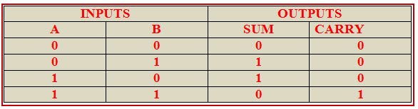
Now it has been cleared that 1-bit adder can be easily implemented with the help of the XOR Gate for the output ‘SUM’ and an AND Gate for the ‘Carry’. When we need to add, two 8-bit bytes together, we can be done with the help of a full-adder logic. The half-adder is useful when you want to add one binary digit quantities. A way to develop a two-binary digit adders would be to make a truth table and reduce it. When you want to make a three binary digit adder, do it again. When you decide to make a four digit adder, do it again. The circuits would be fast, but development time is slow.
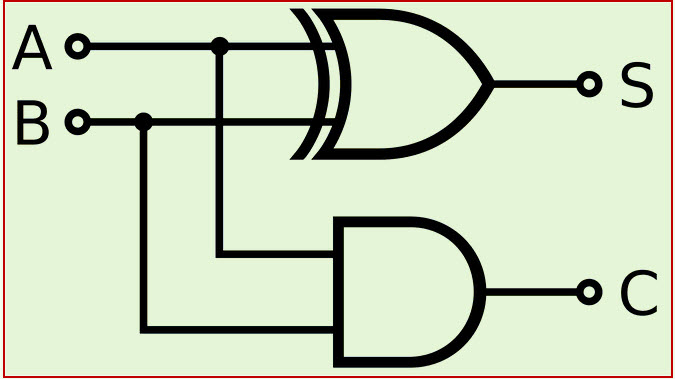
The simplest expression uses the exclusive OR function: Sum=AÅB. An equivalent expression in terms of the basic AND, OR, and NOT is: SUM=A|.B+A.B’
VHDL Code For half Adder
entity ha is
Port (a: in STD_LOGIC;
b : in STD_LOGIC;
sha : out STD_LOGIC;
cha : out STD_LOGIC);
end ha;
architecture Behavioral of ha is
begin
sha <= a xor b ;
cha <= a and b ;
end Behavioral
Full Adder
This adder is difficult to implement than a half-adder. The difference between a half-adder and a full-adder is that the full-adder has three inputs and two outputs, whereas half adder has only two inputs and two outputs. The first two inputs are A and B and the third input is an input carry as C-IN. When a full-adder logic is designed, you string eight of them together to create a byte-wide adder and cascade the carry bit from one adder to the next.
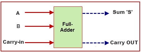
The output carry is designated as C-OUT and the normal output is designated as S.
Full Adder Truth Table:
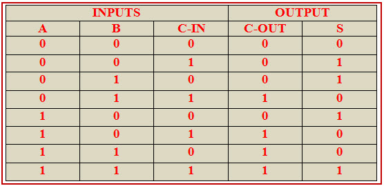
With the truth-table, the full adder logic can be implemented. You can see that the output S is an XOR between the input A and the half-adder, SUM output with B and C-IN inputs. We take C-OUT will only be true if any of the two inputs out of the three are HIGH.
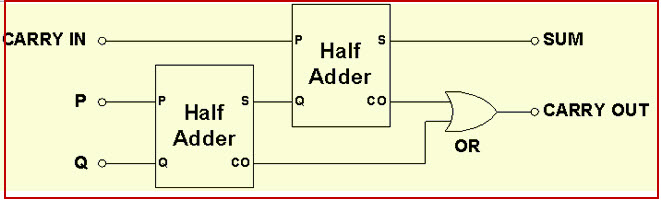
So, we can implement a full adder circuit with the help of two half adder circuits. At first, half adder will be used to add A and B to produce a partial Sum and a second half adder logic can be used to add C-IN to the Sum produced by the first half adder to get the final S output.
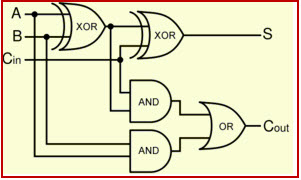
If any of the half adder logic produces a carry, there will be an output carry. So, COUT will be an OR function of the half-adder Carry outputs. Take a look at the implementation of the full adder circuit shown below.
The implementation of larger logic diagrams is possible with the above full adder logic a simpler symbol is mostly used to represent the operation. Given below is a simpler schematic representation of a one-bit full adder.
With this type of symbol, we can add two bits together, taking a carry from the next lower order of magnitude, and sending a carry to the next higher order of magnitude. In a computer, for a multi-bit operation, each bit must be represented by a full adder and must be added simultaneously. Thus, to add two 8-bit numbers, you will need 8 full adders which can be formed by cascading two of the 4-bit blocks.
Combinational circuit combines the different gates in the circuit for example encoder, decoder, multiplexer and demultiplexer. Characteristics of combinational circuits are as follows.
- The output at any instant of time, depends only on the levels present at input terminals.
- It does not use any memory. The previous state of input does not have any effect on the present state of the circuit.
- It can have a number of inputs and m number of outputs.
The relationship between the Full-Adder and the Half-Adder is half adder produces results and full adder uses half adder to produce some other result. Similarly, while the Full-Adder is of two Half-Adders, the Full-Adder is the actual block that we use to create the arithmetic circuits.
